13 Results
View results:
Sort by:

In many frame and truss structures, it is no longer sufficient to use a simple member. You often have to consider cross-section weakenings or openings in solid beams. In such cases, you can use the "Surface Model" member type. It can be integrated into the model like any other member and offers all the options of a surface model. The present technical article shows the application of such a member in an existing structural system and describes the integration of member openings.

Inserting holes in surfaces is very easy due to the large selection of tools. In order to insert holes or drilling in solids, it is necessary to keep in mind that an opening at the beginning and the end of a continuous hole must be created, as well as a surface that separates the hole from the solids.
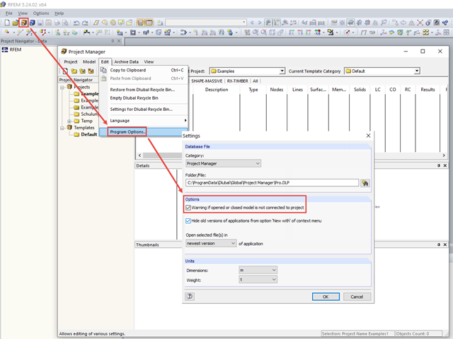
Warning Regarding Connection to Project
---
When opening a model immediately after opening the program, there is a message window asking if you want to create a new project for the model in the Project Manager.
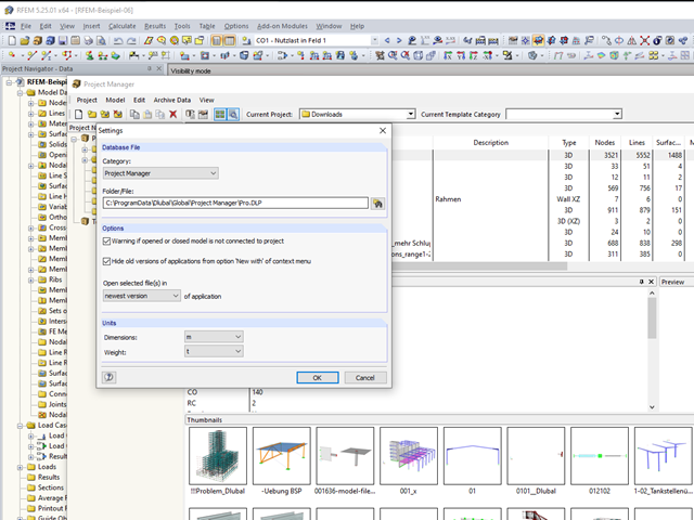
In RFEM and RSTAB, you can work with the Project Manager. It allows you to create an entire project structure and to connect it with the folders on the local hard disk.
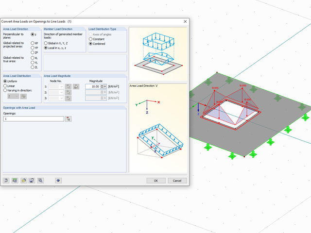
With the "Convert Area Loads on Openings to Line Loads" function, you can automatically take into account, for example, wind loads applied on windows or other loads applied on non‑bearing structures not represented in the model in openings. You can access this function via "Tools" → "Generate Loads" → "From Area Loads on Openings...."
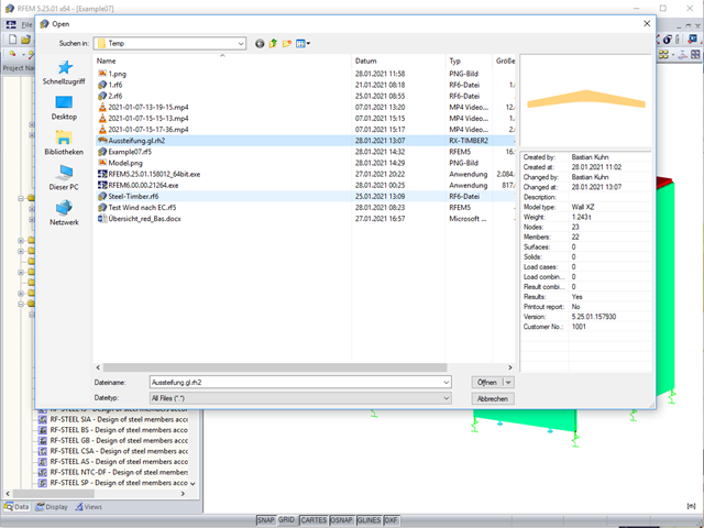
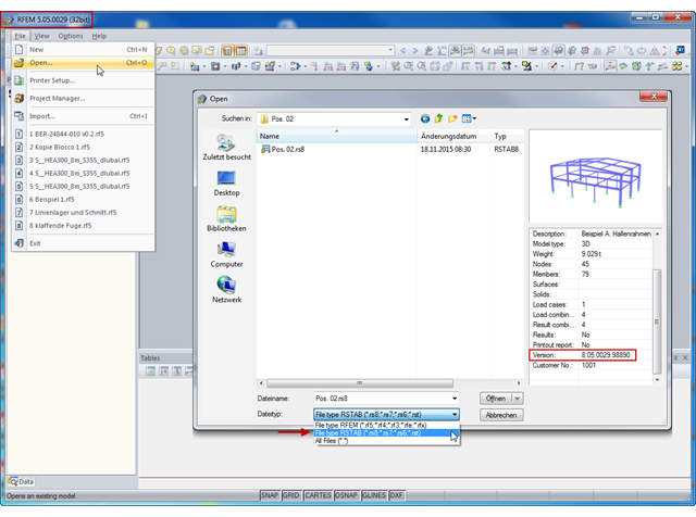
To open an RX‑TIMBER file in RFEM 5 or RSTAB 8, select the "All Files (*.*)" option as "File Type".
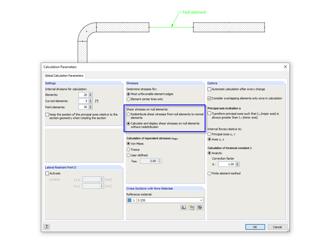
In cross‑sections created in SHAPE‑THIN, the openings, such as bolt holes, can be modeled by using the elements with zero thickness. The program provides two options for calculating shear stresses in the area of such null elements.

According to Book 631 of the DAfStb (German Committee for Structural Concrete), Chapter 2.4, the structural behavior of ceilings changes if their continuous support by walls is interrupted in areas of openings. Depending on the length of the opening area and the plate thickness, measures are necessary regarding the analysis of the ceiling in the area of the opening.
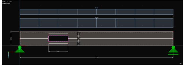
Since the ultimate limit state of beams in the area of openings is affected, particular attention should be paid to this. In general, small openings can be sufficiently covered by adapting the beam structure to the openings. For big openings, it is necessary to consider and model the area separately.
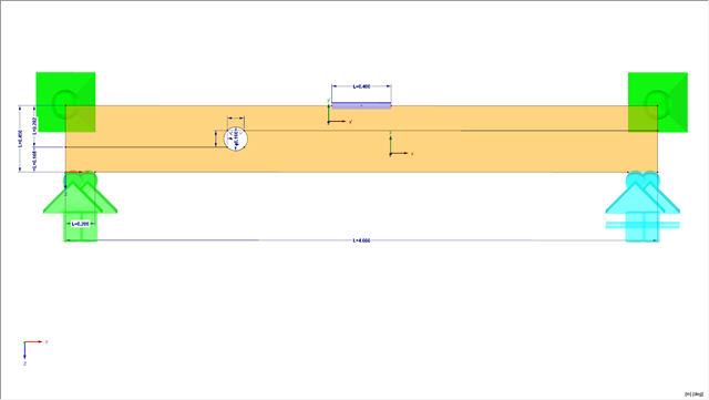
This article presents a bending beam with a circular opening analyzed using the numerical method. As a reference point, there is an example of a perforated beam from [1]. In our case, the 3D model was simplified to a two-dimensional discretization.
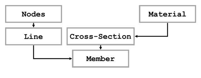
The first part of the article series about the COM interface described opening and creating a model in RFEM. The second part explains creating and modifying elements on an example of a member. The elements described in Part 1 will not be explained again here.
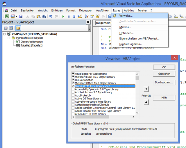
The first part of the post about the COM interface describes opening and closing RFEM. VBA programming language is used in Excel; however, the program sequence is the same as for programming with C#. First, it is necessary to add the corresponding reference in VBA to recognize the commands for the interface. The image on the left shows an example of RFEM 5.
In RFEM, you can open and further edit structures with loads and load cases that have been modeled in RSTAB. For example, this may be necessary if you realize during the model input that it is useful to include surface elements such as wall surfaces and others in the existing RSTAB model.